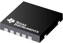
Datasheet Texas Instruments TPS54620RHLR — Ficha de datos
| Fabricante | Texas Instruments |
| Serie | TPS54620 |
| Numero de parte | TPS54620RHLR |

Entrada de 4.5V a 17V, convertidor SWIFT ™ descendente síncrono de 6A 14-VQFN -40 a 150
Hojas de datos
TPS54620 4.5-V to 17-V Input, 6-A, Synchronous, Step-Down SWIFTв„ў Converter datasheet
PDF, 2.1 Mb, Revisión: F, Archivo publicado: mayo 23, 2017
Extracto del documento
Precios
Estado
| Estado del ciclo de vida | Activo (Recomendado para nuevos diseños) |
| Disponibilidad de muestra del fabricante | Sí |
Embalaje
| Pin | 14 |
| Package Type | RHL |
| Industry STD Term | VQFN |
| JEDEC Code | S-PQFP-N |
| Package QTY | 3000 |
| Carrier | LARGE T&R |
| Device Marking | 54620 |
| Width (mm) | 3.5 |
| Length (mm) | 3.5 |
| Thickness (mm) | .9 |
| Pitch (mm) | .5 |
| Max Height (mm) | 1 |
| Mechanical Data | Descargar |
Paramétricos
| Control Mode | Current Mode |
| Duty Cycle(Max) | 98 % |
| Iout(Max) | 6 A |
| Iq(Typ) | 0.6 mA |
| Operating Temperature Range | -40 to 150 C |
| Package Group | VQFN |
| Rating | Catalog |
| Regulated Outputs | 1 |
| Special Features | Enable,Frequency Synchronization,Power Good,Pre-Bias Start-Up,Synchronous Rectification,Tracking |
| Switching Frequency(Max) | 1600 kHz |
| Switching Frequency(Min) | 200 kHz |
| Type | Converter |
| Vin(Max) | 17 V |
| Vin(Min) | 4.5 V |
| Vout(Max) | 15 V |
| Vout(Min) | 0.8 V |
Plan ecológico
| RoHS | Obediente |
Kits de diseño y Módulos de evaluación
- Evaluation Modules & Boards: DLPLCR4500EVM
DLPВ® LightCrafterВ™ 4500
Estado del ciclo de vida: Activo (Recomendado para nuevos diseños) - Evaluation Modules & Boards: DLPLCR9000EVM
DLPВ® LightCrafterВ™ 9000 Evaluation Module
Estado del ciclo de vida: Activo (Recomendado para nuevos diseños) - Evaluation Modules & Boards: DLPLCR6500EVM
DLPВ® LightCrafterВ™ 6500 Evaluation Module
Estado del ciclo de vida: Activo (Recomendado para nuevos diseños) - Evaluation Modules & Boards: TPS54620EVM-374
TPS54620 8V to 17V, 6A SWIFTВ™ Converter Evaluation Module
Estado del ciclo de vida: Activo (Recomendado para nuevos diseños) - Evaluation Modules & Boards: EVMK2G
66AK2Gx (K2G) Evaluation Module
Estado del ciclo de vida: Activo (Recomendado para nuevos diseños)
Notas de aplicación
- Ultra Small 5A, Adjustable Output Reference design using TPS54620PDF, 711 Kb, Archivo publicado: mayo 21, 2010
- Create an Inverting Power Supply Using a Synchronous Step-Down Regulator (Rev. A)PDF, 911 Kb, Revisión: A, Archivo publicado: jun 18, 2012
- Measuring the Junction Temperature of the TPS54620PDF, 119 Kb, Archivo publicado: enero 14, 2010
- TPS54620 Parallel OperationPDF, 412 Kb, Archivo publicado: marzo 3, 2010
The TPS54620 is a synchronous, step-down, dc-dc converter with integrated high- and low-side FETs. It is rated for a continuous output of 6 A. In order to increase the output current capability, it is possible to operate two TPS54620 circuits in parallel. Certain techniques are required in the design to ensure that each of the TPS54620 converters provides an equal share of the output current. T - Minimizing Output Ripple During StartupPDF, 675 Kb, Archivo publicado: jun 22, 2017
A buck DC/DC switching converter has a minimum on-time at which it can operate. This limits theminimum output voltage a converter can regulate to while keeping a fixed frequency. The limitation of theminimum on-time is often only considered for the steady-state output voltage; however, when the outputvoltage ramps up, in most cases the output voltage ramps up from 0 V. When the converter tri - Not All Jitter Is Created Equal (Rev. A)PDF, 555 Kb, Revisión: A, Archivo publicado: jul 4, 2015
This application report offers a tutorial discussion on jitter in switching DC-DC converters. Not all power supply designs are equally susceptible to jitter, nor are they equally affected by jitter. Modes of switching jitter are defined and explained for several popular control architectures, which are then analyzed for sources of jitter. An example contrasting the amount of jitter and effect on o - Calculating EfficiencyPDF, 175 Kb, Archivo publicado: feb 19, 2010
This application report provides a step-by-step procedure for calculating buck converter efficiency and power dissipation at operating points not provided by the data sheet. - Designing Type III Compensation for Current Mode Step-Down Converters (Rev. A)PDF, 298 Kb, Revisión: A, Archivo publicado: sept 15, 2010
One of the well-known benefits of current-mode control is that the system stability can be easily achieved by Type II compensation design. It is possible to improve the transient response of a current mode DC/DC converter by adopting Type III compensation to boost the crossover frequency and phase margin. Type III compensation is simple to design and needs only one extra component. - Demystifying Type II and Type III Compensators Using Op-Amp and OTA for DC/DC CoPDF, 782 Kb, Archivo publicado: jul 11, 2014
- Understanding Thermal Dissipation and Design of a HeatsinkPDF, 59 Kb, Archivo publicado: mayo 4, 2011
Power dissipation performance must be well understood prior to integrating devices on a printed-circuit board (PCB) to ensure that any given device is operated within its defined temperature limits. When a device is running, it consumes electrical energy that is transformed into heat. Most of the heat is typically generated by switching devices like MOSFETs, ICs, etc. This application report discu
Linea modelo
Serie: TPS54620 (5)
- 905-5462001 TPS54620RGYR TPS54620RGYT TPS54620RHLR TPS54620RHLT
Clasificación del fabricante
- Semiconductors > Power Management > Non-isolated DC/DC Switching Regulator > Step-Down (Buck) > Buck Converter (Integrated Switch)