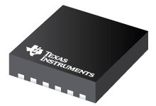
Datasheet Texas Instruments TPS54020RUWR — Ficha de datos
| Fabricante | Texas Instruments |
| Serie | TPS54020 |
| Numero de parte | TPS54020RUWR |

Entrada de 4.5V a 17V, Convertidor SWIFT ™ sincrónico reductor de 10A con sincronización fuera de fase 15-VQFN-HR -40 a 150
Hojas de datos
TPS54020 Small, 10-A, 4.5-V to 17-V Input, SWIFTв„ў Synchronous Step-Down Converter With Light-Load Efficiency datasheet
PDF, 2.3 Mb, Revisión: D, Archivo publicado: dic 12, 2014
Extracto del documento
Precios
Estado
| Estado del ciclo de vida | Activo (Recomendado para nuevos diseños) |
| Disponibilidad de muestra del fabricante | Sí |
Embalaje
| Pin | 15 |
| Package Type | RUW |
| Industry STD Term | VQFN-HR |
| JEDEC Code | S-PQFP-N |
| Package QTY | 3000 |
| Carrier | LARGE T&R |
| Device Marking | 54020 |
| Width (mm) | 3.5 |
| Length (mm) | 3.5 |
| Thickness (mm) | .9 |
| Pitch (mm) | .5 |
| Max Height (mm) | 1 |
| Mechanical Data | Descargar |
Paramétricos
| Control Mode | Current Mode |
| Duty Cycle(Max) | 98 % |
| Iout(Max) | 10 A |
| Iq(Typ) | 0.6 mA |
| Operating Temperature Range | -40 to 150 C |
| Package Group | VQFN-HR |
| Rating | Catalog |
| Regulated Outputs | 1 |
| Special Features | Adjustable Current Limit,Enable,Frequency Synchronization,Light Load Efficiency,Phase Interleaving,Power Good,Pre-Bias Start-Up,Synchronous Rectification,Tracking |
| Switching Frequency(Max) | 1200 kHz |
| Switching Frequency(Min) | 200 kHz |
| Type | Converter |
| Vin(Max) | 17 V |
| Vin(Min) | 4.5 V |
| Vout(Max) | 5 V |
| Vout(Min) | 0.6 V |
Plan ecológico
| RoHS | Obediente |
| Pb gratis | Sí |
Kits de diseño y Módulos de evaluación
- Evaluation Modules & Boards: TPS54020EVM-082
10A Synchronous Step-Down SWIFTВ™ Converter Evaluation Module
Estado del ciclo de vida: Activo (Recomendado para nuevos diseños)
Notas de aplicación
- Designing a negative boost converter from a standard positive buck converterPDF, 267 Kb, Archivo publicado: abr 16, 2013
- HotRod QFN Application NotePDF, 356 Kb, Archivo publicado: abr 9, 2014
HotRod Quad flatpack No Leads (QFN) are leadless packages specifically designed for power applications. The small footprint, standard QFN pitch, low parasitics along with high current capability of these packages are ideal for power converters application. The electrical connections are made via lands on the bottom side of the component to the surface of the connecting substrate (PCB). This applic - Calculating EfficiencyPDF, 175 Kb, Archivo publicado: feb 19, 2010
This application report provides a step-by-step procedure for calculating buck converter efficiency and power dissipation at operating points not provided by the data sheet. - 2Q 2013 Issue Analog Applications JournalPDF, 2.5 Mb, Archivo publicado: abr 16, 2013
- SMT Guidelines for Stacked Inductor (Inductor On Top) on Voltage Regulator ICPDF, 409 Kb, Archivo publicado: feb 22, 2016
- Understanding Thermal Dissipation and Design of a HeatsinkPDF, 59 Kb, Archivo publicado: mayo 4, 2011
Power dissipation performance must be well understood prior to integrating devices on a printed-circuit board (PCB) to ensure that any given device is operated within its defined temperature limits. When a device is running, it consumes electrical energy that is transformed into heat. Most of the heat is typically generated by switching devices like MOSFETs, ICs, etc. This application report discu - Semiconductor and IC Package Thermal Metrics (Rev. C)PDF, 201 Kb, Revisión: C, Archivo publicado: abr 19, 2016
Linea modelo
Serie: TPS54020 (2)
- TPS54020RUWR TPS54020RUWT
Clasificación del fabricante
- Semiconductors > Power Management > Non-isolated DC/DC Switching Regulator > Step-Down (Buck) > Buck Converter (Integrated Switch)